Fluid Catalytic Cracking (FCC) is the conversion process used in petroleum refineries to convert the high-boiling point, high-molecular weight hydrocarbon fractions of petroleum (crude oils) into gasoline, olefinic gases, and other petroleum products.The cracking of petroleum hydrocarbons was originally done by thermal cracking, now almost replaced by catalytic cracking, which yields greater volumes of high octane rating gasoline; and produces by-product gases, with more carbon-carbon double bonds (i.e. olefins), that are of greater economic value than the gases produced by thermal cracking.
The feedstock to the FCC conversion process usually is heavy gas oil (HGO), which is that portion of the petroleum (crude oil) that has an initial boiling-point temperature of 340 °C (644 °F) or higher, at atmospheric pressure, and that has an average molecular weight that ranges from about 200 to 600 or higher; heavy gas oil also is known as “heavy vacuum gas oil” (HVGO). In the fluid catalytic cracking process, the HGO feedstock is heated to a high temperature and to a moderate pressure, and then is placed in contact with a hot, powdered catalyst, which breaks the long-chain molecules of the high-boiling-point hydrocarbon liquids into short-chain molecules, which then are collected as a vapor.
Economics
Oil refineries use fluid catalytic cracking to correct the imbalance between the market demand for gasoline and the excess of heavy, high boiling range products resulting from the distillation of crude oil.
As of 2006, FCC units were in operation at 400 petroleum refineries worldwide, and about one-third of the crude oil refined in those refineries is processed in an FCC to produce high-octane gasoline and fuel oils.During 2007, the FCC units in the United States processed a total of 5,300,000 barrels (840,000 m3) per day of feedstock and FCC units worldwide processed about twice that amount.
FCC units are less common in EMEA because those regions have high demand for diesel and kerosene, which can be satisfied with hydrocracking. In the US, fluid catalytic cracking is more common because the demand for gasoline is higher.
Flow diagram and process description
The modern FCC units are all continuous processes which operate 24 hours a day for as long as 3 to 5 years between scheduled shutdowns for routine maintenance.
There are several different proprietary designs that have been developed for modern FCC units. Each design is available under a license that must be purchased from the design developer by any petroleum refining company desiring to construct and operate an FCC of a given design.
There are two different configurations for an FCC unit: the “stacked” type where the reactor and the catalyst regenerator are contained in two separate vessels, with the reactor above the regenerator, with a skirt between these vessels allowing the regenerator off-gas piping to connect to the top of the regenerator vessel, and the “side-by-side” type where the reactor and catalyst regenerator are in two separate vessels. The stacked configuration occupies less physical space of the refinery area. These are the major FCC designers and licensors:
Side-by-side configuration:
CB&I
ExxonMobil Research and Engineering (EMRE)
Shell Global Solutions
Axens / Stone & Webster Process Technology — currently owned by Technip
UOP LLC – A Honeywell Company
Stacked configuration:
Kellogg Brown & Root (KBR)
Each of the proprietary design licensors claims to have unique features and advantages. A complete discussion of the relative advantages of each of the processes is beyond the scope of this article.
Reactor and regenerator
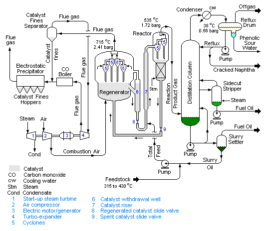
The reactor and regenerator are considered to be the heart of the fluid catalytic cracking unit. The schematic flow diagram of a typical modern FCC unit in Figure 1 below is based upon the “side-by-side” configuration. The preheated high-boiling petroleum feedstock (at about 315 to 430 °C) consisting of long-chain hydrocarbon molecules is combined with recycle slurry oil from the bottom of the distillation column and injected into the catalyst riser where it is vaporised and cracked into smaller molecules of vapour by contact and mixing with the very hot powdered catalyst from the regenerator. All of the cracking reactions take place in the catalyst riser within a period of 2–4 seconds. The hydrocarbon vapours “fluidize” the powdered catalyst and the mixture of hydrocarbon vapors and catalyst flows upward to enter the reactor at a temperature of about 535 °C and a pressure of about 1.72 bar.
The reactor is a vessel in which the cracked product vapors are: (a) separated from the spent catalyst by flowing through a set of two-stage cyclones within the reactor and (b) the spent catalyst flows downward through a steam stripping section to remove any hydrocarbon vapors before the spent catalyst returns to the catalyst regenerator. The flow of spent catalyst to the regenerator is regulated by a slide valve in the spent catalyst line.
Since the cracking reactions produce some carbonaceous material (referred to as catalyst coke) that deposits on the catalyst and very quickly reduces the catalyst reactivity, the catalyst is regenerated by burning off the deposited coke with air blown into the regenerator. The regenerator operates at a temperature of about 715 °C and a pressure of about 2.41 bar, hence the regenerator operates at about 0.7 bar higher pressure than the reactor. The combustion of the coke is exothermic and it produces a large amount of heat that is partially absorbed by the regenerated catalyst and provides the heat required for the vaporization of the feedstock and the endothermic cracking reactions that take place in the catalyst riser. For that reason, FCC units are often referred to as being ‘heat balanced’.
The hot catalyst (at about 715 °C) leaving the regenerator flows into a catalyst withdrawal well where any entrained combustion flue gases are allowed to escape and flow back into the upper part to the regenerator. The flow of regenerated catalyst to the feedstock injection point below the catalyst riser is regulated by a slide valve in the regenerated catalyst line. The hot flue gas exits the regenerator after passing through multiple sets of two-stage cyclones that remove entrained catalyst from the flue gas.
The amount of catalyst circulating between the regenerator and the reactor amounts to about 5 kg per kg of feedstock, which is equivalent